28 KiB
| layout | title |
|---|---|
| documentation | ZW175 - ZWave |
{% include base.html %}
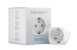
ZW175 Smart Switch 7
This describes the Z-Wave device ZW175, manufactured by Aeotec Limited with the thing type UID of aeotec_zw175_00_000.
The device is in the category of Power Outlet, defining Small devices to be plugged into a power socket in a wall which stick there.
The ZW175 supports routing. This allows the device to communicate using other routing enabled devices as intermediate routers. This device is also able to participate in the routing of data between other devices in the mesh network.
Overview
Aeotec Smart Switch 7 (SS7) has been crafted to power connected lighting using SmartStart, S2 framework, and Z-Wave Plus. It is powered by Aeotec’s S2 technology.
-
Smart Switch 7 is intended for indoor use in dry locations only. Do not use in damp, moist, and/or wet locations.
-
Max-amperage: 15 amps for ZW175-A
-
Max-amperage: 15 amps for ZW175-B
-
Max-amperage: 10 amps for ZW175-C
Inclusion Information
Getting your Smart Switch up and running is as simple as plugging it into a wall socket and adding it to your Z-Wave network.
- Set your Z-Wave Controller into its 'Add Device' mode in order to add the product into your Z-Wave system. Refer to the Controller's manual if you are unsure of how to perform this step.
- Power your Smart Switch 7 to any outlet; its LED will be breathing a blue light if it is ready to be paired.
- Click Action Button 2 times slowly to set your Smart Switch 7 into pair mode.
- If your Z-Wave Controller supports S2 encryption, enter the first 5 digits of DSK into your Controller's interface if it is requested. The DSK is printed on its Smart Switch 7.
a) If pairing succeeds, it will become a bright blue light for 2 seconds. Smart Switch 7 is now a part of your Z-Wave home control system. You can configure it and its automation via your Z-Wave system; please refer to your software's user guide for precise instructions.
b) If pairing fails, it will light a solid bright red light for 2 seconds and then return to a breathing blue light; repeat steps 1 to 4 if this happens.
Exclusion Information
Your Smart Switch can be removed from your Z-Wave network at any time. You’ll need to use your Z-Wave network’s main controller to do this and the following instructions will tell you how to do this using Aeotec by Aeon Labs’ Z-Stick or Minimote controller.
If you are using other products as your main Z-Wave controller, please refer to the part of their respective manuals that tells you how to remove devices from your network.
If you're using an existing gateway:
- Set your Z-Wave Controller into its 'Remove Device' / 'Unpair Device' mode in order to remove the product from your Z-Wave system. Refer to the Controller's manual if you are unsure of how to perform this step.
- Make sure the product is powered. If not, plug it into a wall socket and power it on.
- Click Action Button 2 times quickly; it will bright violet light up to 2s.
a. If Removing fails, it will bright red light for 2 seconds and then turn back to Load Indicator Mode; repeat steps 1 to 3. Contact us for further support if needed.
b. If Removing succeeds, it will become breathing blue light. Smart Switch 7 is removed from the Z-Wave network successfully and is ready to be paired again.
General Usage Information
Button Presses and LED reaction.
<td>
  <strong>Function when released.</strong>
</td>

<td>
  <strong>LED Reaction</strong>
</td>
<td>
  (Unpaired from the network).<br /><br />(Paired into the network).
</td>

<td>
  Breathes blue.<br /><br />LED follows the state of load (configurable).
</td>
<td>
  Pairs into Z-Wave network.
</td>

<td>
  Blue fast blink during pairing, then solid blue for 2 seconds to indicate success.
</td>
<td>
  <br />Controls load state.<br /><br />
</td>

<td>
  LED Follows load control state.
</td>
<td>
  Enters pair mode.
</td>

<td>
  Blue fast blink, after first Click Red and after second Click Orange.<br /><br />The LED change to Green, if the device paired<br /><br /><br />
</td>
<td>
  Enters unpair mode
</td>

<td>
  After press 2 times the led indicate purple.<br /><br />After inclusion, the LED flashes Blue
</td>
<td>
  Disable the Alarm Response
</td>

<td>
  LED stops flash
</td>
<td>
  Toggles LED display mode when SS7 is paired.
</td>

<td>
  Yellow LED

  <ul>
    <li>
      Enabled - LED follows ON/OFF state.
    </li>
    <li>
      Disabled - LED is disabled
    </li>
  </ul>
</td>
<td>
  Test communication quality
</td>

<td>
  Indicator Light will become cyan light when press, and quickly flash cyan light when release, indicating start to test communication quality between the product and Node 1.

  <p>
    At the end of the test, Indicator Light will display the colour according to the communication quality.
  </p>

  <p>
    Good = green light for 2s.
  </p>

  <p>
    General = yellow light for 2s.
  </p>

  <p>
    Poor = red light for 2s.
  </p>
</td>
<td>
  Reset overload alarm and over current Alarm
</td>

<td>
  Red LED flashes
</td>
<td>
  Stay in Z-Wave network, but factory resets all settings back to default.
</td>

<td>
  Red LED Flashes faster.
</td>
<td>
  Completely factory reset and remove from Z-Wave network.
</td>

<td>
  Breathes Blue.
</td>
| Button Press |
| Power On |
| QR Code Scan |
| Tap or Click |
| Press 2 times slowly |
| Press 2 times fastly |
| Press 3 times |
| Press and hold for 2 to 5 seconds. |
| Press and hold for 5 to 10 seconds. |
| Press and hold for 10 to 15 seconds. |
| Press and hold for 15 to 20 seconds. |
| Press and hold for 20 seconds and more. |
Channels
The following table summarises the channels available for the ZW175 -:
| Channel Name | Channel ID | Channel Type | Category | Item Type |
|---|---|---|---|---|
| Switch | switch_binary | switch_binary | Switch | Switch |
| LED Control | switch_dimmer | switch_dimmer | DimmableLight | Dimmer |
| Scene Number | scene_number | scene_number | Number | |
| Electric meter (amps) | meter_current | meter_current | Energy | Number |
| Electric meter (kWh) | meter_kwh | meter_kwh | Energy | Number |
| Electric meter (watts) | meter_watts | meter_watts | Energy | Number |
| Electric meter (volts) | meter_voltage | meter_voltage | Energy | Number |
| Reset Meter | meter_reset | meter_reset | Energy | Switch |
| Color Control | color_color | color_color | ColorLight | Color |
| Color Temperature | color_temperature | color_temperature | ColorLight | Dimmer |
| Alarm (power) | alarm_power | alarm_power | Energy | Switch |
| Alarm (system) | alarm_system | alarm_system | Switch | |
| Clock Time Offset | time_offset | time_offset | Time | Number |
Switch
Switch the power on and off.
The switch_binary channel is of type switch_binary and supports the Switch item and is in the Switch category.
LED Control
The brightness channel allows to control the brightness of a light. It is also possible to switch the light on and off.
The switch_dimmer channel is of type switch_dimmer and supports the Dimmer item and is in the DimmableLight category.
Scene Number
Triggers when a scene button is pressed.
The scene_number channel is of type scene_number and supports the Number item.
Electric meter (amps)
Indicates the instantaneous current consumption.
The meter_current channel is of type meter_current and supports the Number item and is in the Energy category. This is a read only channel so will only be updated following state changes from the device.
Electric meter (kWh)
Indicates the energy consumption (kWh).
The meter_kwh channel is of type meter_kwh and supports the Number item and is in the Energy category. This is a read only channel so will only be updated following state changes from the device.
Electric meter (watts)
Indicates the instantaneous power consumption.
The meter_watts channel is of type meter_watts and supports the Number item and is in the Energy category. This is a read only channel so will only be updated following state changes from the device.
Electric meter (volts)
Indicates the instantaneous voltage.
The meter_voltage channel is of type meter_voltage and supports the Number item and is in the Energy category. This is a read only channel so will only be updated following state changes from the device.
Reset Meter
Reset the meter.
The meter_reset channel is of type meter_reset and supports the Switch item and is in the Energy category.
Color Control
The color channel allows to control the color of a light. It is also possible to dim values and switch the light on and off.
The color_color channel is of type color_color and supports the Color item and is in the ColorLight category.
Color Temperature
The color temperature channel allows to set the color temperature of a light from 0 (cold) to 100 (warm).
The color_temperature channel is of type color_temperature and supports the Dimmer item and is in the ColorLight category.
Alarm (power)
Indicates if a power alarm is triggered.
The alarm_power channel is of type alarm_power and supports the Switch item and is in the Energy category. This is a read only channel so will only be updated following state changes from the device.
The following state translation is provided for this channel to the Switch item type -:
| Value | Label |
|---|---|
| OFF | OK |
| ON | Alarm |
Alarm (system)
Indicates if a system alarm is triggered.
The alarm_system channel is of type alarm_system and supports the Switch item. This is a read only channel so will only be updated following state changes from the device.
The following state translation is provided for this channel to the Switch item type -:
| Value | Label |
|---|---|
| OFF | OK |
| ON | Alarm |
Clock Time Offset
Provides the current time difference for the devices time.
The time_offset channel is of type time_offset and supports the Number item and is in the Time category.
Device Configuration
The following table provides a summary of the 16 configuration parameters available in the ZW175. Detailed information on each parameter can be found in the sections below.
| Param | Name | Description |
|---|---|---|
| 4 | Overload threshold | Set Watt (W) Threshold for Overpower. |
| 8 | Switch reaction to alarm | What do to when an alarm is recieved |
| 9 | Alarm reaction when received | Configure what alarms Smart Switch 7 will react to from other Z-Wave devices. |
| 10 | Release/Disable alarm | Sets how you are able to disable Smart Switch 7s alarm state |
| 18 | Flash frequency | Configures the LED flash frequency and amount of time |
| 19 | Start/Stop LED flash | Sets the timeframe of flashing in seconds |
| 20 | Power restored state | Switches state after an power outage |
| 80 | Status Update | Determine which reports are sent to your gateway |
| 81 | LED indicator mode | Allows you to configure how the LED indicator works |
| 82 | Night Light Mode | Enable or disable Night Light Mode during specific times |
| 91 | Watt threshold | When to send a watt report |
| 92 | kWh threshold | When to send a kWh report |
| 93 | Current threshold | When to send a current report |
| 101 | Timed report enable/disable | Configure timed report |
| 111 | Timed report interval | Reports the sensors set on Parameter 101 |
| 255 | Factory reset | Factory reset the smart switch 7 |
Parameter 4: Overload threshold
Set Watt (W) Threshold for Overpower. If power exceeds the value set in this parameter for over 1 minute, Smart Switch 7 will report and overload report and turn off Smart Switch 7. Values in the range 0 to 2415 may be set.
The manufacturer defined default value is 2415.
This parameter has the configuration ID config_4_2 and is of type INTEGER.
Parameter 8: Switch reaction to alarm
What do to when an alarm is recieved Set the response of the switch in response to an operation performed when an alarm is received. The following option values may be configured -:
| Value | Description |
|---|---|
| 0 | No Action |
| 1 | Turn switch off |
| 2 | Turn switch on |
| 3 | Turn the switch on and off |
The manufacturer defined default value is 0 (No Action).
This parameter has the configuration ID config_8_1 and is of type INTEGER.
Parameter 9: Alarm reaction when received
Configure what alarms Smart Switch 7 will react to from other Z-Wave devices.
<td>
  <strong>Description</strong>
</td>
<td>
  The alarm will be triggered by open state, and be disabled by closed state.
</td>
<td>
  The alarm will be triggered by closed state, and be disabled by open state.
</td>
<td>
  Smoke alarm.
</td>
<td>
  CO Alarm
</td>
<td>
  CO2 Alarm
</td>
<td>
  Heat Alarm
</td>
<td>
  Water Alarm
</td>
<td>
  Access Control
</td>
<td>
  Home Security
</td>
| Value |
| 1 |
| 256 |
| 512 |
| 1024 |
| 2048 |
| 4096 |
| 8192 |
| 16384 |
Value 0 and 1 cannot be used at the same time, choose one as a part of your calculation.
Use the sum of values to determine what alarms trigger your Smart Switch 7.
For example:
Value = 0 + 256 + 512 + 1024 = 1792
0 = sets the control scheme to turn on Smart Switch 7 when open alarm state happens
256 = allows Smoke Alarm signals to control SS7
512 = allows CO Alarm signals to control SS7
1024 = allows CO2 Alarm signals to control SS7This is an advanced parameter and will therefore not show in the user interface without entering advanced mode. The following option values may be configured, in addition to values in the range 0 to 32513 -:
| Value | Description |
|---|---|
| 0 | Trigger open, disabled closed |
| 1 | Trigger closed, disabled open |
| 256 | Smoke alarm |
| 512 | CO Alarm |
| 1024 | CO2 Alarm |
| 2048 | Heat Alarm |
| 4096 | Water Alarm |
| 8192 | Access Control |
| 16384 | Home Security |
The manufacturer defined default value is 0 (Trigger open, disabled closed).
This parameter has the configuration ID config_9_2 and is of type INTEGER.
Parameter 10: Release/Disable alarm
Sets how you are able to disable Smart Switch 7s alarm state
<td>
  <strong>Description</strong>
</td>
<td>
  Tap 3 times to disable the alarm state.
</td>
<td>
  Notification idle events.
</td>
<td>
  Sets time in minutes on how long the alarm state should be held.
</td>
| Value |
| 1 |
| 10 - 255 |
The manufacturer defined default value is 0.
This parameter has the configuration ID config_10_1 and is of type INTEGER.
Parameter 18: Flash frequency
Configures the LED flash frequency and amount of time
<td>
  <strong>Description</strong>
</td>
<td>
  Sets the flash frequency in seconds. (Default = 0x0002 or 2)
</td>
| Byte Value |
|
(MSB Value 1) 1 - 9 |
The manufacturer defined default value is 2.
This parameter has the configuration ID config_18_2 and is of type INTEGER.
Parameter 19: Start/Stop LED flash
Sets the timeframe of flashing in seconds
Values in the range 0 to 255 may be set.
The manufacturer defined default value is 0.
This parameter has the configuration ID config_19_2_wo and is of type INTEGER.
This is a write only parameter.
Parameter 20: Power restored state
Switches state after an power outage Sets which state Smart Switch 7 switches to when power is lost then restored (power outage)
<td>
  <strong>Description</strong>
</td>
<td>
  Last known state. (restore state before power loss)
</td>
<td>
  Power restored to ON.
</td>
<td>
  <p>
    Power restored to OFF.
  </p>
</td>
|
Value |
| 1 |
| 2 |
The manufacturer defined default value is 0.
This parameter has the configuration ID config_20_1 and is of type INTEGER.
Parameter 80: Status Update
Determine which reports are sent to your gateway Keeps the status of Smart Switch 7 in sync with your Z-Wave gateway. Determine which reports are sent to your gateway upon a state change (ie. If switch turns ON, then the switch will forward state update to Z-Wave gateway).
Size = 1 Byte
Default Setting = 2
<td>
  <strong>Description</strong>
</td>
<td>
  No report sent.
</td>
<td>
  Report Basic Report.
</td>
<td>
  Report Binary Switch.
</td>
| Value |
| 1 |
| 2 |
| Value | Description |
|---|---|
| 0 | No report sent |
| 1 | Report Basic Report |
| 2 | Report Binary Switch |
The manufacturer defined default value is 2 (Report Binary Switch).
This parameter has the configuration ID config_80_1 and is of type INTEGER.
Parameter 81: LED indicator mode
Allows you to configure how the LED indicator works
<td>
  Description
</td>
<td>
  LED Disabled.
</td>
<td>
  Night Light Mode.

  <ul>
    <li>
      Use Parameter 82 to configure Night Light timing.
    </li>
    <li>
      Brightness can be controlled via Multilevel Switch CC.
    </li>
    <li>
      Colour can be controlled via Color Switch CC.
    </li>
  </ul>
</td>
<td>
  On/Off Mode.

  <ul>
    <li>
      Default use <ul>
        <li>
          ON = 50% white light
        </li>
        <li>
          OFF = 10% green light
        </li>
      </ul>
    </li>

    <li>
      Brightness can be controlled via Multilevel Switch CC.
    </li>
    <li>
      Colour can be controlled via Color Switch CC.
    </li>
  </ul>
</td>
| Value |
| 1 |
| 2 |
| Value | Description |
|---|---|
| 0 | LED Disabled |
| 1 | Night Light Mode |
| 2 | On/Off Mode |
The manufacturer defined default value is 2 (On/Off Mode).
This parameter has the configuration ID config_81_1 and is of type INTEGER.
Parameter 82: Night Light Mode
Enable or disable Night Light Mode during specific times
<td>
  ON Hour (0 - 23)
</td>
<td>
  ON Minute (0 - 59)
</td>
<td>
  OFF Hour (0 - 23)
</td>
<td>
  OFF Minute (0 - 59)
</td>
| Value 1 |
| Value 2 |
| Value 3 |
| Value 4 |
Byte value = 0x**(Value 1)(Value 2)(Value 3)(Value 4)**
Suggestion - use a hexadecimal to decimal converter that can be easily found on google.
For example:
If you want to set Night Light Mode to be enabled at 19:00 at night and disable at 07:30 in the morning, you just need to configure:
Value1=0x13, Value2=0x00, Value3=0x07, Value4=0x1E.
Input 0x1300071E into a hexadecimal calculator, the output decimal value will be 318768926 Values in the range 0 to 0 may be set.
The manufacturer defined default value is 0.
This parameter has the configuration ID config_82_4 and is of type INTEGER.
Parameter 91: Watt threshold
When to send a watt report If Watt passes the threshold setting by + or -, a Watt report will be sent to update its value.
<td>
  <strong>Description</strong>
</td>
<td>
  Disable Watt threshold.
</td>
<td>
  Watt threshold setting.
</td>
| Value |
| 1 - 2300 |
The manufacturer defined default value is 0.
This parameter has the configuration ID config_91_2 and is of type INTEGER.
Parameter 92: kWh threshold
When to send a kWh report If kWh passes the threshold setting by + or -, a kWh report will be sent to update its value.
<td>
  <strong>Description</strong>
</td>
<td>
  Disable kWh threshold.
</td>
<td>
  kWh threshold setting.
</td>
| Value |
| 1 - 10000 |
The manufacturer defined default value is 100.
This parameter has the configuration ID config_92_2 and is of type INTEGER.
Parameter 93: Current threshold
When to send a current report If current passes the threshold setting by + or -, a current report will be sent to update its value.
<td>
  <strong>Description</strong>
</td>
<td>
  Disable Current threshold.
</td>
<td>
  Current threshold setting by scale of 0.1A
</td>
| Value |
| 1 - 100 |
If value 10 is set, this is the equivalent of setting threshold to 1.0A. Values in the range 0 to 100 may be set.
The manufacturer defined default value is 0.
This parameter has the configuration ID config_93_1 and is of type INTEGER.
Parameter 101: Timed report enable/disable
Configure timed report Sets what sensors should be reported at a timed interval. This can be used at the same time as threshold reporting to allow both thresholds and timed reports to be used.
<td>
  <strong>Description</strong>
</td>
<td>
  kWh (Accumulated Power)
</td>
<td>
  Watt (Power used at the time of the report)
</td>
<td>
  Current
</td>
<td>
  Voltage
</td>
| Value |
| 1 |
| 2 |
| 4 |
| 8 |
The values in the table above should be added together.
For example:
If you want kWh and Watt only, you would add 1 + 2 = 3.
If you want all values (current, voltage, watt, kWh) reported at an interval, you would add 1 + 2 + 4 + 8 = 15.
If 0 is set to this parameter setting, this would completely disable timed reports. (Parameter 111 does not need to be set). Values in the range 0 to 15 may be set.
The manufacturer defined default value is 0.
This parameter has the configuration ID config_101_4 and is of type INTEGER.
Parameter 111: Timed report interval
Reports the sensors set on Parameter 101 Reports the sensors set on Parameter 101.
Size = 4 Byte
Default Setting = 600
<td>
  <strong>Description</strong>
</td>
<td>
  Interval set in seconds.
</td>
| Value |
| 30 - 2592000 |
The manufacturer defined default value is 600.
This parameter has the configuration ID config_111_4 and is of type INTEGER.
Parameter 255: Factory reset
Factory reset the smart switch 7 This value can only be configured to reset default values of Smart Switch 7 parameter settings. This can also be used to factory reset and remove it from your Z-Wave network.
<td>
  <strong>Description</strong>
</td>
<td>
  Do nothing.
</td>
<td>
  Reset Parameter Settings to default settings.
</td>
<td>
  Completely factory reset and remove from network.
</td>
| Value |
| Any value within 4 bytes. |
| 0x55555555 or 1431655765 |
The manufacturer defined default value is 0.
This parameter has the configuration ID config_255_4 and is of type INTEGER.
Association Groups
Association groups allow the device to send unsolicited reports to the controller, or other devices in the network. Using association groups can allow you to eliminate polling, providing instant feedback of a device state change without unnecessary network traffic.
The ZW175 supports 1 association group.
Group 1: Group 1
load notification type (lifeline)
Association group 1 supports 5 nodes.
Technical Information
Endpoints
Endpoint 0
| Command Class | Comment |
|---|---|
| COMMAND_CLASS_NO_OPERATION_V1 | |
| COMMAND_CLASS_BASIC_V1 | |
| COMMAND_CLASS_APPLICATION_STATUS_V1 | |
| COMMAND_CLASS_SWITCH_BINARY_V1 | Linked to BASIC |
| COMMAND_CLASS_SWITCH_MULTILEVEL_V2 | |
| COMMAND_CLASS_SCENE_ACTIVATION_V1 | |
| COMMAND_CLASS_SCENE_ACTUATOR_CONF_V1 | |
| COMMAND_CLASS_METER_V3 | |
| COMMAND_CLASS_SWITCH_COLOR_V1 | |
| COMMAND_CLASS_ASSOCIATION_GRP_INFO_V1 | |
| COMMAND_CLASS_DEVICE_RESET_LOCALLY_V1 | |
| COMMAND_CLASS_ZWAVEPLUS_INFO_V1 | |
| COMMAND_CLASS_CONFIGURATION_V1 | |
| COMMAND_CLASS_ALARM_V4 | |
| COMMAND_CLASS_MANUFACTURER_SPECIFIC_V1 | |
| COMMAND_CLASS_POWERLEVEL_V1 | |
| COMMAND_CLASS_PROTECTION_V2 | |
| COMMAND_CLASS_FIRMWARE_UPDATE_MD_V1 | |
| COMMAND_CLASS_CLOCK_V1 | |
| COMMAND_CLASS_ASSOCIATION_V2 | |
| COMMAND_CLASS_VERSION_V2 | |
| COMMAND_CLASS_SECURITY_V1 |
Documentation Links
Did you spot an error in the above definition or want to improve the content? You can contribute to the database here.