7.8 KiB
| layout | title |
|---|---|
| documentation | Minoston - ZWave |
{% include base.html %}
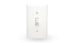
Minoston Toggle Dimmer Switch
This describes the Z-Wave device Minoston, manufactured by NIE Technology with the thing type UID of nietech_minoston_00_000.
The device is in the category of Wall Switch, defining Any device attached to the wall that controls a binary status of something, for ex. a light switch.
The Minoston supports routing. This allows the device to communicate using other routing enabled devices as intermediate routers. This device is also able to participate in the routing of data between other devices in the mesh network.
Overview
Transform any home into a smart home with the Z-Wave Smart Switch. The switch enables you to wirelessly control to turn lights on and off, schedule a timed event or create a custom scene from anywhere in the world, at any time of the day. Take control of your home lighting with Z-Wave Smart Lighting Controls
Inclusion Information
Make your controller/hub into the "inclusion" mode, triple press the Up/Down push button quickly to include it in the network.
Exclusion Information
Make your controller/hub into the "exclusion" mode, triple press the Up/Down push button quickly to exclude it from the network.
Channels
The following table summarises the channels available for the Minoston -:
| Channel Name | Channel ID | Channel Type | Category | Item Type |
|---|---|---|---|---|
| Dimmer | switch_dimmer | switch_dimmer | DimmableLight | Dimmer |
| Scene Number | scene_number | scene_number | Number |
Dimmer
The brightness channel allows to control the brightness of a light. It is also possible to switch the light on and off.
The switch_dimmer channel is of type switch_dimmer and supports the Dimmer item and is in the DimmableLight category.
Scene Number
Triggers when a scene button is pressed.
The scene_number channel is of type scene_number and supports the Number item.
This channel provides the scene, and the event as a decimal value in the form <scene>.<event>. The scene number is set by the device, and the event is as follows -:
| Event ID | Event Description |
|---|---|
| 0 | Single key press |
| 1 | Key released |
| 2 | Key held down |
| 3 | Double keypress |
| 4 | Tripple keypress |
| 5 | 4 x keypress |
| 6 | 5 x keypress |
Device Configuration
The following table provides a summary of the 6 configuration parameters available in the Minoston. Detailed information on each parameter can be found in the sections below.
| Param | Name | Description |
|---|---|---|
| 1 | Locally Button Function | LED flashes 2 times when the configuration parameter changed. |
| 2 | LED Indicator | LED flashes 2 times |
| 4 | Auto Turn-Off Timer | Auto Turn-Off Timer |
| 6 | Auto Turn-On Timer | Auto Turn-On Timer |
| 7 | Association Setting Parameter | Association Setting Parameter |
| 8 | Restores state after power failure | Restores state after power failure |
Parameter 1: Locally Button Function
LED flashes 2 times when the configuration parameter changed. Locally Button function(quickly press 7x)
Value=0 Up Button: On/Down Button: Off(Default)
Value=1 Up Button: Off/Down Button: On
Value=2 Up Button: On/Off/Down Button: On/Off
---Parameter 1: Choose if you want the upper paddle to turn the light on or turn the light off when tapped, or if you'd like any paddle to change the state of the light.
Values: 0 – Upper paddle turns the light on, lower paddle turns the light off (default);
Values: 1 – Upper paddle turns the light off, lower paddle turns the light on;
Values: 2 – any paddle changes the state of the light. Values in the range 0 to 2 may be set.
The manufacturer defined default value is 0.
This parameter has the configuration ID config_1_1 and is of type INTEGER.
Parameter 2: LED Indicator
LED flashes 2 times LED Indicator(quickly press 6x)
Value=0 On when output Off and Off when output On (default)
Value=1 On when output On and Off when output Off
Value=2 Always Off Values in the range 0 to 2 may be set.
The manufacturer defined default value is 0.
This parameter has the configuration ID config_2_1 and is of type INTEGER.
Parameter 4: Auto Turn-Off Timer
Auto Turn-Off Timer Values: 0 – 65535 (minutes); 0 (minutes) – default setting Values in the range 0 to 65535 may be set.
The manufacturer defined default value is 0.
This parameter has the configuration ID config_4_4 and is of type INTEGER.
Parameter 6: Auto Turn-On Timer
Auto Turn-On Timer Values: 0 – 65535 (minutes); 0 (minutes) – default setting Values in the range 0 to 65535 may be set.
The manufacturer defined default value is 0.
This parameter has the configuration ID config_6_4 and is of type INTEGER.
Parameter 7: Association Setting Parameter
Association Setting Parameter
- Value=00 – none
- Value=01 - local
- Value=02 - 3way
- Value=03 - 3way & local
- Value=04 - z-wave hub
- Value= Value=05 - z-wave hub & local
- Value=06 - z-wave hub & 3-way
- Value=07 - z-wave hub & local & 3way
- Value=08 - timer
- Value=09 - timer & local
- Value=10 - timer & 3-way
- Value=11 - timer & 3-way & local
- Value=12 - timer & z-wave hub
- Value=13 - timer & z-wave hub & local
- Value=14 - timer & z-wave hub & 3-way
- Value=15 - all Values in the range 0 to 15 may be set.
The manufacturer defined default value is 1.
This parameter has the configuration ID config_7_1 and is of type INTEGER.
Parameter 8: Restores state after power failure
Restores state after power failure
Value=0 output off
Value=1 output on
Value=2 output the state after power
Values in the range 0 to 2 may be set.
The manufacturer defined default value is 2.
This parameter has the configuration ID config_8_1 and is of type INTEGER.
Association Groups
Association groups allow the device to send unsolicited reports to the controller, or other devices in the network. Using association groups can allow you to eliminate polling, providing instant feedback of a device state change without unnecessary network traffic.
The Minoston supports 2 association groups.
Group 1: Lifeline
The Lifeline association group reports device status to a hub and is not designed to control other devices directly. When using the Lineline group with a hub, in most cases, only the lifeline group will need to be configured and normally the hub will perform this automatically during the device initialisation.
Association group 1 supports 1 node.
Group 2: Send Basic Set ON / Off
Association group 2 supports 5 nodes.
Technical Information
Endpoints
Endpoint 0
| Command Class | Comment |
|---|---|
| COMMAND_CLASS_NO_OPERATION_V1 | |
| COMMAND_CLASS_BASIC_V1 | |
| COMMAND_CLASS_SWITCH_MULTILEVEL_V3 | Linked to BASIC |
| COMMAND_CLASS_ASSOCIATION_GRP_INFO_V1 | |
| COMMAND_CLASS_DEVICE_RESET_LOCALLY_V1 | |
| COMMAND_CLASS_CENTRAL_SCENE_V3 | |
| COMMAND_CLASS_ZWAVEPLUS_INFO_V1 | |
| COMMAND_CLASS_CONFIGURATION_V1 | |
| COMMAND_CLASS_MANUFACTURER_SPECIFIC_V1 | |
| COMMAND_CLASS_POWERLEVEL_V1 | |
| COMMAND_CLASS_FIRMWARE_UPDATE_MD_V1 | |
| COMMAND_CLASS_ASSOCIATION_V2 | |
| COMMAND_CLASS_VERSION_V2 | |
| COMMAND_CLASS_MULTI_CHANNEL_ASSOCIATION_V3 |
Documentation Links
Did you spot an error in the above definition or want to improve the content? You can contribute to the database here.