20 KiB
| layout | title |
|---|---|
| documentation | ZW141 - ZWave |
{% include base.html %}
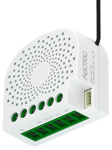
ZW141 Nano Shutter
This describes the Z-Wave device ZW141, manufactured by Aeotec Limited with the thing type UID of aeotec_zw141_03_000.
This version of the device is limited to firmware versions above 3.0
The device is in the category of Blinds, defining Roller shutters, window blinds, etc..
The ZW141 supports routing. This allows the device to communicate using other routing enabled devices as intermediate routers. This device is also able to participate in the routing of data between other devices in the mesh network.
Overview
Aeotec Nano Shutter is a Z-Wave motor controller specifically used to enable Z-Wave command and control (up/down/stop) for existing window covering motors. It can connect to 2 external manual switches/buttons to control the motor up/down/stop independently.
Its surface has a pin socket, which can be used for connecting to the touch panel, so you can also use the touch panel to control the Nano Shutter.
The wireless module is powered from the mains supply. In the event of power failure, non-volatile memory retains all programmed information relating to the units operating status. Nano Shutter is also a security Z-Wave plus device and supports Over The Air (OTA) feature for the products firmware upgrade.
It can be a repeater in the Z-Wave network. Acting as a bridge for communication, it will forward Z-Wave command messages to their destinations if the originating controller is out of range from the destination node.
Inclusion Information
- Set your Z-Wave controller into pairing mode.
- Press the Action Button on the Nano Dimmer or toggle the external manual switch once, the green LED (non-secure indication) will blink to indicate the Nano Dimmer is entering into pairing mode.
- If the Nano Dimmer has been successfully added to your Z-Wave network, its RGB LED will be solid. If the pairing was unsuccessful, the red LED will be on for 2 seconds and then remain a colourful gradient, repeat the instructions above from step 1.
Exclusion Information
- Set your Z-Wave controller into removal mode.
- Press the Action Button 6 times on the Nano Dimmer or toggle the external manual switch 2 times in fast succession.
- If the Nano Dimmer has been successfully removed from your Z-Wave network, its RGB LED will remain colourful gradient. If the removal was unsuccessful, the RGB LED will still be solid (following the state of the output load), repeat the instructions above from step 1.
General Usage Information
Controlling the Nano Shutter.
- Use any of the below methods to control the Nano Shutter.
- Pressing the button on the external (Wall) switch will be able to spin the motor up/down/stop through the usage of Z-Wave commands built into Z-Wave certified controllers and gateways (The specific Z-Wave commands supporting this function are the Basic Command Class and Multilevel Switch Command Class.) Please consult the operation manual for these controllers for specific instructions on controlling the Motor Controller.
- A short press on the button on the Motor Controller will spin the motor up/down/stop.
- Change Mode on the External Switch/Button Control.
- Nano Shutter by default is set to be controlled via 2-state (flip/flop) external wall switch.
- Pushing the button 6 times in quick succession on the Nano Shutter will swap between this default mode and the momentary push button external wall switch mode
Reset your Nano Shutter
- If at some stage, your primary controller is missing or inoperable, you may wish to reset all of your Nano Shutter’s settings to their factory defaults. To do this, press and hold the Action Button for 20 seconds and then release it. Your Nano Shutter will now be reset to its original settings, and the green LED will be solid for 2 seconds and then remain the colourful gradient status as a confirmation.
Channels
The following table summarises the channels available for the ZW141 -:
| Channel Name | Channel ID | Channel Type | Category | Item Type |
|---|---|---|---|---|
| Blinds Control | blinds_control | blinds_control | Blinds | Rollershutter |
| Scene Number | scene_number | scene_number | Number |
Blinds Control
Provides start / stop control of blinds.
The blinds_control channel is of type blinds_control and supports the Rollershutter item and is in the Blinds category.
Scene Number
Triggers when a scene button is pressed.
The scene_number channel is of type scene_number and supports the Number item.
Device Configuration
The following table provides a summary of the 19 configuration parameters available in the ZW141. Detailed information on each parameter can be found in the sections below.
| Param | Name | Description |
|---|---|---|
| 20 | Motor Behaviour | Motor behavior after Power ON |
| 22 | Motor Direction | Determine motor run direction for Shutter Mode and Venetian Mode |
| 34 | Blade Turn Time | Blade Turn Time (Unit = 0.01 seconds) |
| 35 | Curtain Trip Time (Unit = 0.01 seconds) | Curtain Trip Time |
| 36 | Enter/Exit Calibration | Enter/Exit Calibration |
| 37 | Calibration Confirmation | User confirmation for calibration (Set Only) |
| 38 | Calibration Status | Return Calibration Status (Get or Report) |
| 39 | Curtain Mode | Set curtain mode |
| 40 | Set Begin Repositioning | Set Begin Repositioning |
| 41 | Get repositioning status | |
| 42 | Calibration Lock | Used to enable/disable calibration lock |
| 80 | Report Type | Choose which report to send when switch status change |
| 85 | External Switch Mode | Set External Button Operation Mode |
| 120 | Type External Switch 1 | Set Switch Type of External Switch 1 |
| 121 | Type External Switch 2 | Set Switch Type of External Switch 2 |
| 243 | Get DSK from product | To Get DSK from product |
| 248 | Enable/Disable External Switches | Enable/disable function of external switches S1 & S2 |
| 251 | Reset to Factory / Exclusion Function | Reset to Factory / Exclusion Function |
| 255 | Reset function | Reset function |
Parameter 20: Motor Behaviour
Motor behavior after Power ON
The following option values may be configured -:
| Value | Description |
|---|---|
| 0 | Stay (Default) |
| 1 | Moves to 99% |
| 2 | Moves to 0% |
The manufacturer defined default value is 0 (Stay (Default)).
This parameter has the configuration ID config_20_1 and is of type INTEGER.
Parameter 22: Motor Direction
Determine motor run direction for Shutter Mode and Venetian Mode Determine motor run direction for Shutter mode and Venetian Mode:
<td>
  Function
</td>
<td>
  Shutter mode / Venetian mode :Out 1= Up moving/ Multilevel<br />switch = 99%, Out 2= Down moving/ Multilevel switch = 0%
</td>
<td>
  Shutter mode : Out 1= Down moving/ Multilevel switch = 0%,<br />Out 2= Up moving/ Multilevel switch = 99%.<br />Venetian mode :Out 1= Up moving/ Multilevel switch = 99%, Out<br />2= Down moving/ Multilevel switch = 0%
</td>
<td>
  Shutter mode : Out 1= Up moving/ Multilevel switch = 99%, Out<br />2= Down moving/ Multilevel switch = 0%<br />Venetian mode: Out 1= Down moving/ Multilevel switch = 0%,<br />Out 2= Up moving/ Multilevel switch = 99%.
</td>
<td>
  Shutter mode / Venetian mode : Out 1= Down moving/<br />Multilevel switch = 0%, Out 2= Up moving/ Multilevel switch =<br />99%.
</td>
| Mode / Value |
| 1 |
| 2 |
| 3 |
Note:
1.Motor will stop when receiving this command in moving;
2.This configuration will not change after network exclusion.
The following option values may be configured -:
| Value | Description |
|---|---|
| 0 | Mode 0 (Default) |
| 1 | Mode 1 |
| 2 | Mode 2 |
| 3 | Mode 3 |
The manufacturer defined default value is 0 (Mode 0 (Default)).
This parameter has the configuration ID config_22_1 and is of type INTEGER.
Parameter 34: Blade Turn Time
Blade Turn Time (Unit = 0.01 seconds) Note:
- For Venetian, if this value is set too large for blade turning, curtain may move upwards or downwards.
- Calibration need to work correctly.Or this setting will force the curtain to move up or down.
- This configuration will not change after network exclusion Values in the range 10 to 32767 may be set.
The manufacturer defined default value is 150.
This parameter has the configuration ID config_34_2 and is of type INTEGER.
Parameter 35: Curtain Trip Time (Unit = 0.01 seconds)
Curtain Trip Time Note:
- For Venetian, if this value is set too large for curtain trip, blade turn positioning may cause errors.
- This configuration will not change after network exclusion Values in the range 500 to 32767 may be set.
The manufacturer defined default value is 15000.
This parameter has the configuration ID config_35_2 and is of type INTEGER.
Parameter 36: Enter/Exit Calibration
Enter/Exit Calibration Note:
Product will enter the right Curtain Mode after calibration, see configuration parameter 39. The following option values may be configured -:
| Value | Description |
|---|---|
| 0 | Exit Calibration (Default) |
| 1 | Enter Shutter Mode Calibration |
| 2 | Enter Venetian Mode Calibration |
The manufacturer defined default value is 0 (Exit Calibration (Default)).
This parameter has the configuration ID config_36_1 and is of type INTEGER.
Parameter 37: Calibration Confirmation
User confirmation for calibration (Set Only)
The following option values may be configured -:
| Value | Description |
|---|---|
| 0 | Do Nothing (Default) |
| 1 | Next Step |
The manufacturer defined default value is 0 (Do Nothing (Default)).
This parameter has the configuration ID config_37_1 and is of type INTEGER.
Parameter 38: Calibration Status
Return Calibration Status (Get or Report)
The following option values may be configured -:
| Value | Description |
|---|---|
| 0 | Complete (Default) |
| 1 | -> Reference Point A |
| 2 | -> Reference Point B |
| 3 | Wait |
| 4 | -> Reference Point C |
| 5 | Terminated |
The manufacturer defined default value is 0 (Complete (Default)).
This parameter has the configuration ID config_38_1 and is of type INTEGER.
This is a read only parameter.
Parameter 39: Curtain Mode
Set curtain mode Note:
- This Operation will enter repositioning automatically;
- This configuration will not change after network exclusion The following option values may be configured -:
| Value | Description |
|---|---|
| 0 | Shutter Mode (Default) |
| 1 | Venetian Mode |
The manufacturer defined default value is 0 (Shutter Mode (Default)).
This parameter has the configuration ID config_39_1 and is of type INTEGER.
Parameter 40: Set Begin Repositioning
Set Begin Repositioning
The following option values may be configured -:
| Value | Description |
|---|---|
| 0 | No Action |
| 1 | Begin Repositioning |
The manufacturer defined default value is 0 (No Action).
This parameter has the configuration ID config_40_1 and is of type INTEGER.
Parameter 41: Get repositioning status
The following option values may be configured -:
| Value | Description |
|---|---|
| 0 | Complete |
| 1 | In Repositioning |
The manufacturer defined default value is 0 (Complete).
This parameter has the configuration ID config_41_1 and is of type INTEGER.
This is a read only parameter.
Parameter 42: Calibration Lock
Used to enable/disable calibration lock
The following option values may be configured -:
| Value | Description |
|---|---|
| 0 | Disable |
| 1 | Enable Mode 1 (Default) |
| 2 | Enable Mode 2 |
The manufacturer defined default value is 1 (Enable Mode 1 (Default)).
This parameter has the configuration ID config_42_1 and is of type INTEGER.
Parameter 80: Report Type
Choose which report to send when switch status change
The following option values may be configured -:
| Value | Description |
|---|---|
| 0 | No Report |
| 1 | Basic Report |
| 2 | Multilevel Report |
The manufacturer defined default value is 2 (Multilevel Report).
This parameter has the configuration ID config_80_1 and is of type INTEGER.
Parameter 85: External Switch Mode
Set External Button Operation Mode Set Extern Button Operation Mode
<td>
  Function
</td>
<td>
  S1/S2 map to Z-Wave Button
</td>
<td>
  <p>
    S1 = Open or Stop<br />S2 = Close or Stop
  </p>

  <p>
    Note:Operation will not change the curtain mode, including<br />press and hold ,short press.
  </p>
</td>
<td>
  <ol>
    <li>
      When configuration 0x78/79 = 03:<br />Press and hold S1 :blade folds to 180°<br />Press and hold S2:Blade folds to 0°<br />Short press S1:Blinds go downwards<br />Short press S2:Blinds go upwards<br />Note: The device will change its curtain mode if it does not<br />match the current mode.
    </li>
    <li>
      When Configuration 0x78/79 = others:<br />S1 = Open or Stop<br />S2 = Close or Stop ,operation will not<br />change the curtain mode.
    </li>
  </ol>
</td>
| Value |
| 1 |
| 2 |
Note: when setting value to 2, we advice not to set only one external switch
to push button, do remember to change the controller channel before
operating push button, or the curtain level will be wrong.
The following option values may be configured -:
| Value | Description |
|---|---|
| 0 | Mode 0 (Default) |
| 1 | Mode 1 |
| 2 | Mode 2 |
The manufacturer defined default value is 0 (Mode 0 (Default)).
This parameter has the configuration ID config_85_1 and is of type INTEGER.
Parameter 120: Type External Switch 1
Set Switch Type of External Switch 1 Report automatically during identification
<td>
  In Indentification
</td>
<td>
  Identification succeeded; returns switch type
</td>
<td>
  Identification failed
</td>
| 0x55 |
| 2/3/4 |
| 0x00 |
| Value | Description |
|---|---|
| 0 | Unidentified Mode (Default) |
| 1 | 2-state Switch |
| 2 | 3-way switch |
| 3 | Push Button Mode |
| 4 | Automatic Identification |
The manufacturer defined default value is 0 (Unidentified Mode (Default)).
This parameter has the configuration ID config_120_1 and is of type INTEGER.
Parameter 121: Type External Switch 2
Set Switch Type of External Switch 2 Report automatically during identification
<td>
  In Indentification
</td>
<td>
  Identification succeeded; returns switch type
</td>
<td>
  Identification failed
</td>
| 0x55 |
| 2/3/4 |
| 0x00 |
| Value | Description |
|---|---|
| 0 | Unidentified Mode (Default) |
| 1 | 2-state Switch |
| 2 | 3-way switch |
| 3 | Push Button Mode |
| 4 | Automatic Identification |
The manufacturer defined default value is 0 (Unidentified Mode (Default)).
This parameter has the configuration ID config_121_1 and is of type INTEGER.
Parameter 243: Get DSK from product
To Get DSK from product
Values in the range 0 to 0 may be set.
The manufacturer defined default value is 0.
This parameter has the configuration ID config_243_16 and is of type INTEGER.
This is a read only parameter.
Parameter 248: Enable/Disable External Switches
Enable/disable function of external switches S1 & S2
The following option values may be configured -:
| Value | Description |
|---|---|
| 1 | Enable Network Function (Default) |
| 2 | Enable Reset to Factory |
| 3 | Enable network and reset function |
The manufacturer defined default value is 1 (Enable Network Function (Default) ).
This parameter has the configuration ID config_248_1 and is of type INTEGER.
Parameter 251: Reset to Factory / Exclusion Function
Reset to Factory / Exclusion Function Enable/disable reset to factory default and exclusion function by long press on touch panel and press 6 times on wall swipe The following option values may be configured -:
| Value | Description |
|---|---|
| 0 | Disable |
| 1 | Enable (Default) |
The manufacturer defined default value is 1 (Enable (Default)).
This parameter has the configuration ID config_251_1 and is of type INTEGER.
Parameter 255: Reset function
Reset function
When the command be valid:
1.The Re-Calibration task and Calibration task will be abort if they are
running.
2.The motor will stop if it's workingThis is an advanced parameter and will therefore not show in the user interface without entering advanced mode.
The following option values may be configured -:
| Value | Description |
|---|---|
| 0 | Reset all configuration |
| 1431655765 | Reset to factory default |
The manufacturer defined default value is 0 (Reset all configuration).
This parameter has the configuration ID config_255_4_wo and is of type INTEGER.
This is a write only parameter.
Association Groups
Association groups allow the device to send unsolicited reports to the controller, or other devices in the network. Using association groups can allow you to eliminate polling, providing instant feedback of a device state change without unnecessary network traffic.
The ZW141 supports 2 association groups.
Group 1: Lifeline
The Lifeline association group reports device status to a hub and is not designed to control other devices directly. When using the Lineline group with a hub, in most cases, only the lifeline group will need to be configured and normally the hub will perform this automatically during the device initialisation.
- Device Reset Local ly Notification(0x5A01):
Send after device reset. - Switch Multi level Report (0x2603):
Send after shutter stop moving. - Basic Report(0x2003):
Send after shutter stop moving. (need to set
configuration CC) - Central Scene Notification(0x5B03) :
Send when press S1/S2 - Configuration Report(0x7006):
Send shutter calibration and repositioning status
Association group 1 supports 5 nodes.
Group 2: Retransmit
Retransmit when receiving the follow commands:
BASIC_SET
SWITCH_MULTILEVEL_SET
SWITCH_MULTILEVEL_START_LEVEL_CHANGE
SWITCH_MULTILEVEL_STOP_LEVEL_CHANGE
SCENE_ACTIVATION_SET
Association group 2 supports 5 nodes.
Technical Information
Endpoints
Endpoint 0
| Command Class | Comment |
|---|---|
| COMMAND_CLASS_NO_OPERATION_V1 | |
| COMMAND_CLASS_BASIC_V1 | |
| COMMAND_CLASS_SWITCH_MULTILEVEL_V4 | Linked to BASIC |
| COMMAND_CLASS_SCENE_ACTIVATION_V1 | |
| COMMAND_CLASS_SCENE_ACTUATOR_CONF_V1 | |
| COMMAND_CLASS_ASSOCIATION_GRP_INFO_V1 | |
| COMMAND_CLASS_DEVICE_RESET_LOCALLY_V1 | |
| COMMAND_CLASS_CENTRAL_SCENE_V3 | |
| COMMAND_CLASS_ZWAVEPLUS_INFO_V2 | |
| COMMAND_CLASS_CONFIGURATION_V1 | |
| COMMAND_CLASS_MANUFACTURER_SPECIFIC_V2 | |
| COMMAND_CLASS_POWERLEVEL_V1 | |
| COMMAND_CLASS_FIRMWARE_UPDATE_MD_V4 | |
| COMMAND_CLASS_ASSOCIATION_V2 | |
| COMMAND_CLASS_VERSION_V2 | |
| COMMAND_CLASS_SECURITY_V1 |
Documentation Links
Did you spot an error in the above definition or want to improve the content? You can contribute to the database here.